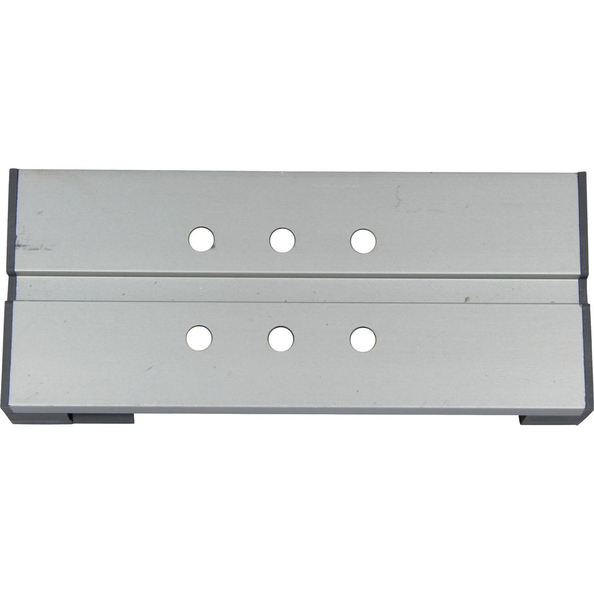


Ultraflex L23 Dual Station Selector Control Unit For 33c Control Cables
Ultraflex L23 Dual Station Selector Control Unit For 33c Control Cables
SKU: AF-4-L23
The Ultraflex L23 / 31649B Dual Station Selector Unit is a mechanical engine-control connector for boats with two operating stations. It allows the same throttle or shift circuit to be operated from either the main station or a secondary station such as a flybridge. Current Uflex product data specify the L23 for inboard and sterndrive engines and state that the throttle must be at idle and the shift in neutral before transferring operation between stations.
Delivery available | lead times vary
Collection available | usually ready in 2-4 days
Description
Description
The Ultraflex L23 / 31649B Dual Station Selector Unit is a mechanical engine-control connector for boats with two operating stations. It allows the same throttle or shift circuit to be operated from either the main station or a secondary station such as a flybridge. Current Uflex product data specify the L23 for inboard and sterndrive engines and state that the throttle must be at idle and the shift in neutral before transferring operation between stations.
A single L23 does not independently control both throttle and shift. The Ultraflex application drawing shows one selector installed in the reverse-gear circuit and a second selector in the throttle circuit. A typical single-engine, two-station installation therefore requires two L23 selector units when both functions are to be controlled from both stations.
Product Identification
- Brand: Ultraflex
- Model: L23
- Manufacturer part number: 31649B
- Product category: Mechanical engine control cable accessory
- Product type: Dual station selector unit
- Alternative descriptions: Twin station connector, dual station control selector or mechanical cable selector
- Control system: Mechanical
- Number of operating stations: Two
- Typical station arrangement: Main cabin and flybridge
- Official control type: Single-lever controls
- Function per selector: One throttle or one shift/reverse-gear circuit
- Typical single-engine system quantity: Two units when both throttle and shift are controlled from both stations
- Engine application: Inboard and sterndrive engines
- Outboard application: Not stated as compatible; current order data specify inboard and sterndrive only
- Control cables connected per selector: Two station control cables, identified as cable “a” and cable “b” in the assembly instructions
- Operating mechanism: Sliding block, guides and cable-retaining assembly
- Station-transfer condition: Throttle at idle and shift in neutral
- Electrical connection: None identified
- Closest Multiflex equivalent: K13 / K-13
- Equivalent status: Functional equivalent; direct interchangeability not manufacturer-confirmed
- Control cables included: No
- Remote control heads included: No
- Engine linkage included: No
- Second selector included: No
- Housing material: Not published
- Overall dimensions: Not published in the manufacturer sources reviewed
- Maximum working load: Not published
What Is the Ultraflex L23 Used For?
The L23 connects the mechanical control cables from two operating stations so that either station can operate the same engine-control function.
It can form part of a correctly specified:
- Dual-station inboard engine control system
- Dual-station sterndrive control system
- Main-cabin and flybridge control installation
- Single-lever dual-station installation
- Throttle selector circuit
- Gear-shift or reverse-gear selector circuit
- Replacement of an existing L23 selector
- New mechanical dual-station installation
- Retrofit where the cable ends, travel and control resistance have been verified
The L23 is an engine control selector. It does not switch or operate the boat’s steering system.
The complete Ultraflex arrangement uses separate selectors for the throttle and reverse-gear circuits. Movement from either station is transferred through the relevant selector to the corresponding engine or gearbox control lever.
What Is Included?
- 1 x Ultraflex L23 / 31649B selector-unit assembly
The Ultraflex assembly instructions identify the following constituent parts or mechanisms:
- Preassembled base
- Sliding block
- Two guides
- Cable clamp
- Cable-retaining plates or shims
- Upper half-blocks
- Lower half-blocks
- Retaining screws
- Retaining nuts
The instructions describe these components as parts of the selector assembly, but the current product page does not provide a retail packaging checklist or quantities for every loose fastener.
Not included unless expressly stated:
- First-station throttle cable
- Second-station throttle cable
- First-station shift cable
- Second-station shift cable
- Main-station control lever
- Flybridge control lever
- Engine throttle lever
- Gearbox or reverse-gear lever
- Cable-end clevises
- Cable-end ball joints
- Engine-specific cable adapters
- Cable mounting brackets
- Additional installation fasteners
- A second L23 selector
- Steering helm
- Steering cable
- Hydraulic steering components
- Electrical station-selection switch
Which Control Cables Are Compatible?
The current L23 product page and assembly sheet reviewed do not provide a definitive model-by-model cable compatibility list.
The assembly instructions require:
- A first cable with a threaded moving rod onto which the sliding block can be screwed
- Removal of the first cable’s rod seal before fitting the sliding block
- A compatible conduit-end fitting that can be retained by the lower and upper half-blocks
- A second cable that can be secured to the upper side of the sliding block by the supplied clamp plates and screws
- Matching cable travel between both stations
- Correct cable-end geometry at the control heads and engine linkage
- Suitable control resistance
- Adequate bend radius and installation clearance
The cable manufacturer, model, threaded-rod specification, conduit-end dimensions and travel should therefore be confirmed before ordering. A cable being described as 33C, 3300 or universal does not by itself confirm complete L23 compatibility.
Does One L23 Control Both Throttle and Shift?
No. One L23 selector connects the two station cables for one control function.
The manufacturer application drawing shows:
- One L23 selector connected to the reverse-gear or shift circuit
- One L23 selector connected to the throttle circuit
The product description states that the complete selector arrangement enables throttle and shift control from either station, but the application drawing confirms that a separate selector is used for each function.
How Many L23 Selector Units Are Required?
Single engine, two stations, throttle only:
- 1 x L23 selector
Single engine, two stations, shift only:
- 1 x L23 selector
Single engine, two stations, throttle and shift:
- 2 x L23 selectors
- One for throttle
- One for shift or reverse gear
The Ultraflex application sheet reviewed illustrates a single-engine, dual-station arrangement. It does not publish a separate twin-engine component schedule. A twin-engine system should be specified according to the number of separate throttle and shift circuits.
How Does the L23 Selector Work?
- The sliding block is screwed onto the threaded moving rod of cable “a”.
- The rod seal is removed from cable “a” before the sliding block is installed.
- Cable “b” is secured to the top of the sliding block using the retaining plates and screws.
- The guides are inserted through the sliding block.
- The slider and cable assembly are positioned on the preassembled base.
- The cable “a” conduit fitting and the guides are seated in the lower half-blocks.
- The upper half-blocks are installed and secured with the specified screws.
- The completed cable circuit is connected to the relevant throttle or reverse-gear lever.
Movement from either station acts through the sliding block and connected cable assembly to operate the engine or gearbox control.
Is There an Electrical Station-Selection Switch?
No electrical supply, wiring connection, solenoid or electronic selector is identified in the Ultraflex product data or installation drawing.
The L23 is a passive mechanical selector. Its operation depends on the movement of the connected control cables and the resistance of the control levers and engine linkage.
How Should the Active Station Be Changed?
Before transferring operation from one station to the other:
- Return the throttle to the idle position
- Place the shift control in neutral
- Confirm that the corresponding lever at the other station is correctly positioned
- Move the new active station carefully through its initial travel
- Check that the engine or gearbox lever responds rather than dragging the other control head
What Does the Control-Resistance Warning Mean?
The Ultraflex manual explains that L23 operation depends on the difference between the movement resistance of the remote control levers and connected cables and the movement resistance of the engine or reverse-gear lever being operated.
Correct operation is obtained when the resistance at each remote control is greater than the resistance of the engine reverse-gear lever.
Where this relationship is incorrect, moving one station’s control can move the lever at the other station instead of operating the engine or gearbox linkage.
After installation, test operation repeatedly from both stations. Where the inactive control is dragged, increase the control-lever braking or externally retain the dragged lever in neutral in accordance with the Ultraflex instructions.
Is the Multiflex K13 a Direct Equivalent to the Ultraflex L23?
The Multiflex K13 / K-13 is the closest documented functional equivalent.
The two products share:
- Mechanical dual-station operation
- Connection of two operating stations
- One selector per throttle or shift circuit
- Sliding cable-transfer mechanism
- Use with mechanical engine control cables
- Passive operation without an electrical station switch
- Dependence on correct control-lever resistance
- Requirement for repeated testing from both stations
Ultraflex L23:
- Model L23
- Manufacturer part number 31649B
- Officially described for single-lever controls
- Current order data specify inboard and sterndrive engines
- Officially states idle throttle and neutral shift before changing station
- Application drawing reviewed shows a single-engine, two-station arrangement
- Exact cable-model list not published on the current product page
Multiflex K13:
- Item code K13
- Manual designation K-13
- Officially described for universal 3300-series Multiflex cables
- Current product page does not state a specific engine type
- Manual illustrates single-engine and twin-engine two-station arrangements
- Manual identifies a plastic cap and plastic base plate
- Overall dimensions and maximum load are not published
Neither manufacturer source reviewed identifies the other product as an approved direct replacement. Confirm the cable interface, selector length, mounting arrangement, slider travel and installation clearances before substitution.
Can Multiflex K13 Dimensions Be Applied to the L23?
No. Do not assume that the L23 and K13 share their overall length, width, guide spacing, cable-centre spacing, thread size, conduit-end recess, sliding-block travel, mounting-hole positions, fastener sizes or material composition.
Physical measurement or a current manufacturer drawing should be used where installation space is restricted.
Is the L23 Suitable for Outboard Engines?
The current Uflex order details describe the L23 as only for inboard and sterndrive engines. It should not be advertised as an outboard selector unless a current Ultraflex application document specifically approves the intended installation.
Is the L23 for Single-Lever or Two-Lever Controls?
The current Uflex product description specifies single-lever controls in dual-station applications. The selected control heads must still provide suitable resistance, travel and cable attachment geometry.
Does the L23 Control Steering?
No. The L23 is an engine throttle and shift control accessory. It does not replace a mechanical steering helm, steering cable, hydraulic helm, steering cylinder, steering station selector, steering tie bar or autopilot interface.
Dual station refers to two engine-control positions, not to the steering system.
What Are the L23 Dimensions?
The official L23 product page and Ultraflex assembly sheet reviewed do not publish:
- Overall length
- Extended overall length
- Overall width
- Overall height
- Guide-rod diameter
- Guide spacing
- Cable-centre spacing
- Mounting-hole spacing
- Sliding-block travel
- Maximum connected cable stroke
- Product weight
Where replacement fit or enclosed installation space is critical, compare the physical L23 or obtain a current Ultraflex dimensional drawing before ordering.
What Materials Are Used?
The Ultraflex assembly instructions identify the component types but do not publish their material grades.
The manufacturer information reviewed does not state the base material, sliding-block material, guide material, half-block material, cable-clamp material, fastener grade, surface treatment or corrosion-test standard.
Is a Maximum Working Load Published?
No maximum push load, pull load, proof load or fatigue rating is published for the L23 in the manufacturer sources reviewed.
The complete installation must be selected according to the control-cable rating, engine or gearbox operating force, control-lever friction, cable travel, cable routing, linkage geometry and lowest-rated system component.
Construction and Design
- Ultraflex mechanical dual-station selector
- Model L23
- Manufacturer part number 31649B
- Designed for two operating stations
- Intended for single-lever controls
- Current order data specify inboard and sterndrive engines
- Allows operation from a main station or flybridge
- One selector connects one throttle or shift circuit
- Two selectors normally required for single-engine throttle and shift control
- Uses two station control cables per selector
- Sliding-block operating mechanism
- Twin guide arrangement
- Separate cable clamp and retaining plates
- Preassembled base with upper and lower retaining blocks
- Passive mechanical operation
- No electrical supply identified
- Throttle must be at idle before changing station
- Shift must be in neutral before changing station
- Operation depends on correct control-lever resistance
- Cable models not itemised on the current product page
- Control cables supplied separately
- Control heads supplied separately
- Engine connection fittings supplied separately
- Materials not published
- Overall dimensions not published
- Maximum working load not published
- Closest Multiflex functional equivalent: K13
Installation and Safety
- Confirm that the product is L23 / 31649B
- Confirm that the engine is an approved inboard or sterndrive application
- Verify that two-station mechanical control is required
- Determine whether the selector is being used for throttle or shift
- Order one selector for each separate control circuit
- Confirm that the selected control cables fit the L23 assembly
- Check the cable threaded-rod geometry
- Check the conduit-end fitting dimensions
- Confirm matching cable travel
- Confirm sufficient cable-thread engagement
- Remove the cable “a” rod seal only as directed by Ultraflex
- Screw the sliding block onto the threaded rod without cross-threading
- Secure cable “b” using the correct clamp plates and screws
- Position the retaining nuts in their specified locations
- Insert the guides fully through the sliding block
- Seat the guides and cable conduit fitting correctly in the lower half-blocks
- Secure the upper half-blocks evenly
- Route both cables with smooth bends
- Maintain each cable manufacturer’s minimum bend radius
- Avoid side loading at the sliding block
- Avoid twisting the cable rods
- Rig both stations to the same neutral and idle positions
- Return the throttle to idle before changing station
- Place the shift control in neutral before changing station
- Test the throttle circuit repeatedly from both stations
- Test the shift circuit repeatedly from both stations
- Confirm that operating one station does not drag the other station’s lever
- Increase control-lever braking where required by the Ultraflex instructions
- Confirm full throttle, idle, forward, neutral and reverse positions
- Ensure no cable bottoms out before the engine or gearbox lever reaches its stop
- Check every cable clamp and threaded connection
- Replace any bent, loose, cracked, seized or corroded component
- Do not operate the boat if either control station moves unpredictably
Engine throttle and shift systems are safety-critical. Installation and commissioning should be completed by a competent marine technician in accordance with the current Ultraflex, control-box, cable, engine and gearbox instructions.
Key Features
- Ultraflex L23 dual-station control selector
- Manufacturer part number 31649B
- Mechanical engine-control accessory
- Connects two operating stations
- Designed for single-lever controls
- Suitable for inboard engines
- Suitable for sterndrive engines
- Not listed for outboard applications
- Enables engine control from the main station or flybridge
- Can be used for a throttle circuit
- Can be used for a shift or reverse-gear circuit
- One selector required per control function
- Two selectors normally required for single-engine throttle and shift
- Uses a sliding-block and twin-guide mechanism
- No electrical supply required
- Throttle must be at idle before changing station
- Shift must be in neutral before changing station
- Correct operation depends on control-lever resistance
- Both stations must be tested after installation
- Control cables supplied separately
- Control heads supplied separately
- Engine linkage fittings supplied separately
- Closest functional equivalent to Multiflex K13
- No formal L23-to-K13 manufacturer cross-reference published
- Cable-model list not published on the current L23 page
- Material grades not published
- Overall dimensions not published
- Maximum working load not published
| Specification | Value |
|---|---|
| Brand | Ultraflex |
| Model | L23 |
| Product Category | Mechanical Engine Control Cable Accessory |
| Product Type | Dual Station Selector Unit |
| Control System | Mechanical |
| Number of Operating Stations | Two |
| Typical Station Arrangement | Main Station and Flybridge |
| Official Control Type | Single-Lever Controls |
| Engine Application | Inboard and Sterndrive Engines |
| Outboard Application | Not Listed; Current Order Data Specify Inboard and Sterndrive Only |
| Primary Function | Connects Two Stations to One Throttle or Shift Circuit |
| Functions Controlled by One Unit | One — Throttle or Shift / Reverse Gear |
| Typical Quantity for Single Engine, Throttle and Shift | Two Selector Units |
| Station Control Cables per Selector | Two |
| Operating Mechanism | Sliding Block with Twin Guides and Cable Clamp |
| Station-Transfer Requirement | Throttle at Idle and Shift in Neutral |
| Operating Principle | Depends on Correct Resistance Relationship Between Controls and Engine Linkage |
| Electrical Power Required | No Electrical Connection Identified |
| Manufacturer Cable Model List | Not Published on Current L23 Product Page |
| Cable Thread Specification | Not Published in Sources Reviewed |
| Control Cables Included | No |
| Remote Control Heads Included | No |
| Engine Linkage Included | No |
| Second Selector Included | No |
| Housing Material | Not Published |
| Overall Dimensions | Not Published in Manufacturer Sources Reviewed |
| Maximum Working Load | Not Published |
| Closest Multiflex Equivalent | K13 / K-13 Twin Station Control Connector |
| Equivalent Status | Functional Equivalent; Formal Direct Cross-Reference Not Published |
| Direct-Fit Confirmation | Confirm Cable Interface, Selector Travel, Mounting Arrangement, Resistance and Clearance |
Specification
Specification
| Specification | Value |
|---|---|
| Brand | Ultraflex |
| Model | L23 |
| Product Category | Mechanical Engine Control Cable Accessory |
| Product Type | Dual Station Selector Unit |
| Control System | Mechanical |
| Number of Operating Stations | Two |
| Typical Station Arrangement | Main Station and Flybridge |
| Official Control Type | Single-Lever Controls |
| Engine Application | Inboard and Sterndrive Engines |
| Outboard Application | Not Listed; Current Order Data Specify Inboard and Sterndrive Only |
| Primary Function | Connects Two Stations to One Throttle or Shift Circuit |
| Functions Controlled by One Unit | One — Throttle or Shift / Reverse Gear |
| Typical Quantity for Single Engine, Throttle and Shift | Two Selector Units |
| Station Control Cables per Selector | Two |
| Operating Mechanism | Sliding Block with Twin Guides and Cable Clamp |
| Station-Transfer Requirement | Throttle at Idle and Shift in Neutral |
| Operating Principle | Depends on Correct Resistance Relationship Between Controls and Engine Linkage |
| Electrical Power Required | No Electrical Connection Identified |
| Manufacturer Cable Model List | Not Published on Current L23 Product Page |
| Cable Thread Specification | Not Published in Sources Reviewed |
| Control Cables Included | No |
| Remote Control Heads Included | No |
| Engine Linkage Included | No |
| Second Selector Included | No |
| Housing Material | Not Published |
| Overall Dimensions | Not Published in Manufacturer Sources Reviewed |
| Maximum Working Load | Not Published |
| Closest Multiflex Equivalent | K13 / K-13 Twin Station Control Connector |
| Equivalent Status | Functional Equivalent; Formal Direct Cross-Reference Not Published |
| Direct-Fit Confirmation | Confirm Cable Interface, Selector Travel, Mounting Arrangement, Resistance and Clearance |